
The Problem: Everything Measures from Its Own Perspective
Imagine your robot has an RGB-D camera—a camera that captures both color images and depth (distance to each pixel). These are common in robotics: Intel RealSense, Microsoft Kinect, and similar sensors. The camera spots a coffee mug at pixel (320, 240), and the depth sensor says it’s 1.2 meters away. You want the robot arm to pick it up—but the arm doesn’t understand pixels or camera-relative distances. It needs coordinates in its own workspace: “move to position (0.8, 0.3, 0.1) meters from my base.” To convert camera measurements to arm coordinates, you need to know:- The camera’s intrinsic parameters (focal length, sensor size) to convert pixels to a 3D direction
- The depth value to get the full 3D position relative to the camera
- Where the camera is mounted relative to the arm, and at what angle

What’s a Coordinate Frame?
A coordinate frame is simply a point of view—an origin point and a set of axes (X, Y, Z) from which you measure positions and orientations. Think of it like giving directions:- GPS says you’re at 37.7749° N, 122.4194° W
- The coffee shop floor plan says “table 5 is 3 meters from the entrance”
- Your friend says “I’m two tables to your left”
- The camera measures in pixels, or in meters relative to its lens
- The LIDAR measures distances from its own mounting point
- The robot arm thinks in terms of its base or end-effector position
- The world has a fixed coordinate system everything lives in
The Transform Class
TheTransform class at geometry_msgs/Transform.py represents a spatial transformation with:
frame_id- The parent frame namechild_frame_id- The child frame nametranslation- AVector3(x, y, z) offsetrotation- AQuaternion(x, y, z, w) orientationts- Timestamp for temporal lookups
Transform Operations
Transforms can be composed and inverted:Converting to Matrix Form
For integration with libraries like NumPy or OpenCV:Frame IDs in Modules
Modules in DimOS automatically get aframe_id property. This is controlled by two config options in core/module.py:
frame_id- The base frame name (defaults to the class name)frame_id_prefix- Optional prefix for namespacing
The TF Service
Every module has access toself.tf, a transform service that:
- Publishes transforms to the system
- Looks up transforms between any two frames
- Buffers historical transforms for temporal queries
protocol/tf/tf.py and is lazily initialized on first access.
Multi-Module Transform Example
This example demonstrates how multiple modules publish and receive transforms. Three modules work together:- RobotBaseModule - Publishes
world -> base_link(robot’s position in the world) - CameraModule - Publishes
base_link -> camera_link(camera mounting position) andcamera_link -> camera_optical(optical frame convention) - PerceptionModule - Looks up transforms between any frames
skip ansi=false
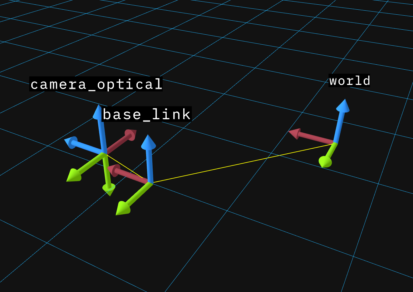 Key points:
- Automatic broadcasting:
self.tf.publish()broadcasts via LCM to all modules - Chained lookups: TF finds paths through the tree automatically
- Inverse lookups: Request transforms in either direction
- Temporal buffering: Transforms are timestamped and buffered (default 10s) for sensor fusion

Internals
Transform Buffer
self.tf on a module is a transform buffer. This is a standalone class that maintains a temporal buffer of transforms (default 10 seconds) allowing queries at past timestamps, you can use it directly:
Further Reading
For a visual introduction to transforms and coordinate frames: For the mathematical foundations, the ROS documentation provides detailed background:- ROS tf2 Concepts
- ROS REP 103 - Standard Units and Coordinate Conventions
- ROS REP 105 - Coordinate Frames for Mobile Platforms
- Modules for understanding the module system
- Configuration for module configuration patterns